
Compressed Air Piping & Professional Installation Services
Optimize your plant footprint with high-performance aluminum and specialized composite air piping manifolds. Our certified engineering layout services guarantee zero-leak drop points, structural friction resistance, and peak pressure maintenance for heavy industrial production grids.
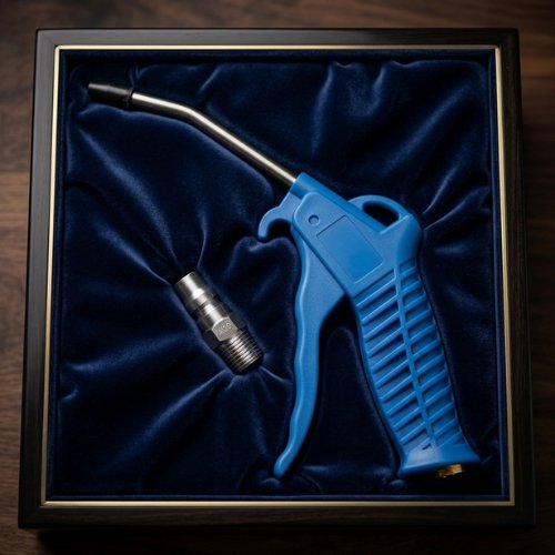
Compressed Air Piping, Fittings & Network Optimization
Welcome to Shiv Industries, your trusted manufacturing partner for leak-free pneumatic infrastructure and inline processing optimization. Our premium distribution fittings, professional layout accessories, and certified engineering systems maximize structural flow velocities while permanently eliminating pressure drops.
Our Premium Product Range
1. High-Flow Quick Release Couplers
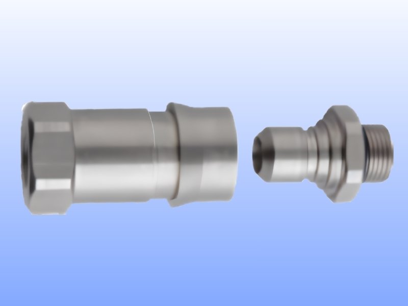
Permanently seal potential drop-point leakage paths with premium-grade **Shiv Industries High-Flow Quick Release Couplers**. Engineered to withstand constant line pressure shocks, these couplings ensure frictionless tool swaps.
How It Works: Engineered with a smooth-bore interior cavity profile, our couplers prevent localized air turbulences. The internal precision check-valves snap closed immediately upon disconnection, blocking any residual line exhaust or sudden pressure drop backward into the sub-header manifolds.
Key Features:
- Durable Solid Brass Construction: Machined from heavy industrial brass stocks to eliminate thread galling, oxidation scaling, and drop damage.
- Universal Fluid & Air Capabilities: Certified for deployment on high-velocity compressed air lines as well as industrial liquid distribution loops.
- Standardized Thread Architecture: Supplied across three distinct industry sizes for flawless inline configuration matching: 1/4", 1/2", and 3/4" BSP threads.
| Thread Parameter | Primary Configuration Application |
|---|---|
| 1/4" BSP Thread | Point-of-Use Air Tooling & Workstation Hose Reels |
| 1/2" BSP Thread | Standard Industrial Machinery & Drop-Line Manifolds |
| 3/4" BSP Thread | Heavy Sub-Header Blocks & High-Volume Supply Lines |
2. Cable & Tube Wiper / Drier (Model: CWR-16 - Real Wipe)
Achieve spotless, rapid line drying on continuous profile processing runs with the high-efficiency **Shiv Industries CWR-16 Real Wipe**. Specifically optimized for installation directly downstream from extrusion cooling baths.
Contactless 360° Drying
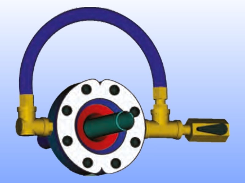
Utilizes a continuous radial air knife boundary layer to shear away water uniformly across the entire outer perimeter of the product without mechanical friction.
Process: Non-Contact Fluid ShearingSpotless Surface Profile
Instantly strips water drops, moisture mist, and residues, ensuring perfectly dry profiles before high-speed printing, marking, or coiling stations.
Result: Zero Water Mark DefectsExtrusion Line Integration
Perfectly configured for rapid deployment on continuous production lines handling industrial wiring, copper cables, plastic pipes, and rubber tubing.
Model: CWR-16 (Real Wipe Series)Pneumatic Technical Resource & Trust Verification Charts
3. The Economic Cost of Compressed Air Leakage
Minor line leaks act as a silent cash drain on plant operations. The metrics detailed below reflect the true financial impact of unnoticed air orifices bleeding out air under a standard continuous operational threshold of **7.0 Bar (approx. 100 PSI)**:
| Orifice Diameter | Air Wasted (CFM) | Power Lost (kW) | Annual Budget Impact |
|---|---|---|---|
| 0.5 mm | 0.45 CFM | 0.1 kW | Minor Line Inefficiency |
| 1.0 mm | 1.80 CFM | 0.4 kW | Measurable Losses |
| 1.5 mm | 7.10 CFM | 1.5 kW | High Cost (Action Required) |
| 3.0 mm | 28.20 CFM | 6.0 kW | Severe Capital Drain |
| 6.0 mm | 113.00 CFM | 24.0 kW | Catastrophic Grid Loss |
4. Pressure Drop Optimization & Sizing Matrix
To safeguard terminal tooling flow requirements, total line distribution layouts must restrict internal friction parameters to limit pressure losses to a maximum ceiling of **0.1 to 0.2 Bar**. Use our verified layout matrix below for header planning:
- Low Flow Volume Loads (0 to 20 CFM Max Input): Use minimum internal header pipe diameters ranging from 1/2" to 3/4" ID for straight system runs below 50 Meters.
- Medium Flow Volume Loads (20 to 100 CFM Input): Demand a minimum header footprint of 1" to 1-1/2" ID to stop extreme localized friction generation.
- High Capacity Main Ring Networks (100+ CFM Input): Require a robust 2" to 3" ID Loop setup to allow multi-directional velocity equalization.
5. Standard Pneumatic Conversion Worksheets
Utilize these certified structural fluid math multipliers when configuring your custom header sizing distributions, receiver tank volumes, or sub-manifold layouts:
- Pneumatic Line Pressure Equivalents:
• 1 Bar = 14.5038 PSI
• 1 Bar = 0.1 MPa = 1.0197 kg/cm² - Volumetric Air Mass Flow Equivalents:
• 1 m³/min = 35.3147 CFM
• 1 CFM = 28.3168 Liters/minute - System Operational Fact: For every single 1 Bar drop in pressure caused by friction or line restrictions, your central compressor is forced to expend **7% more electrical power** to maintain setpoint targets.
Complete Piping Network Auditing
Are you designing a newly constructed industrial manufacturing bay, or planning a complex expansion loop across an existing factory layout? Our specialized application engineering division is standing by to map out your infrastructure blueprint, optimize ring loops, and guarantee zero flow restrictions from the receiver bay down to your terminal machines.
Why Choose Shiv Industries?
Significant Energy Savings
Our advanced air amplification technology reduces up to 70% of plant compressed air footprint.
OSHA Safety Compliance
Strict adherence to regulatory limits for occupational noise and dynamic dead-end backpressure.
100% Spares & Maintenance
Completely serviceable design assemblies with localized ready spare valves, seals, and configurations.
Ready to Optimize Your Compressed Air Efficiency?
Get a customized professional pneumatic system audit and technical specification quote for your plant environment today.